Modbus RTU vs TCP: All you need to know
How Modbus works, how RTU, ASCII, and TCP differ, and what it takes to read Modbus meters remotely
Two Modbus meters can use the same protocol and still require completely different configurations. One exposes a reading in holding registers, another in input registers. One stores a 32-bit value in two registers; another uses a different word order. Modbus standardises the communication, but not the meaning or layout of every meter’s data.
That is the key to understanding Modbus in practice. The protocol is simple, openly documented and supported by a wide range of meters, sensors and controllers. Understanding how Modbus works, how its variants differ and where integration commonly goes wrong can make device integration considerably easier.
Key takeaways
- Modbus is a request and response protocol in which one device asks for data and another answers. The same application layer runs over serial lines as Modbus RTU or ASCII and over TCP/IP networks as Modbus TCP.
- Modbus organises data into four tables: coils, discrete inputs, input registers and holding registers. Function codes define which table is read or written.
- Modbus RTU sends binary frames with a CRC check over a serial line, most often RS-485. Modbus TCP sends the same Modbus data over a TCP connection on port 502, with a 7-byte MBAP header and without the RTU CRC.
- On serial Modbus networks, each slave has an address from 1 to 247, and address 0 is reserved for broadcast commands. Supported broadcast operations are processed without individual responses.
- Modbus standardises communication, but not how manufacturers map measurements to registers. Most integration problems come from register maps, data formats and serial settings rather than from the protocol itself.
- Modbus RTU meters and sensors on RS-485 can be connected to LoRaWAN or NB-IoT through a converter, without replacing the devices.
What Modbus is
Modbus was developed by Modicon, now part of Schneider Electric, in 1979 for its programmable logic controllers. Its specifications are published by the Modbus Organization. At its core, Modbus defines a simple message: a function code that says what to do, followed by the data needed to do it. This message stays the same regardless of how it travels.
What changes between Modbus variants is the frame around that message and the network that carries it. Modbus RTU and Modbus ASCII run over serial lines. Modbus TCP runs over TCP/IP networks, typically Ethernet. A device that speaks one variant does not automatically understand the other, even though the data inside the message is structured identically.
Master and slave, client and server
Modbus communication always follows a request and response pattern. On a serial line, one master initiates every transaction and the slaves respond only when they are addressed. A slave never sends data on its own initiative.
Modbus TCP describes the same roles as client and server. The client sends a request; the server answers. The principle is unchanged, but because TCP/IP is a network rather than a single shared line, several clients can communicate with a server, and the roles are tied to network connections rather than to a position on a bus.
Registers and function codes
Modbus organises data in four tables:
- Coils: single-bit values that can be read and written, typically outputs or switches
- Discrete inputs: single-bit values that can only be read, typically status signals
- Input registers: 16-bit values that can only be read, typically measured values
- Holding registers: 16-bit values that can be read and written, typically settings, parameters and, in many meters, measurement data as well
Function codes tell the device which table to access and how. The basic function codes read each data table and write to those that support writing:
- 01 Read Coils
- 02 Read Discrete Inputs
- 03 Read Holding Registers
- 04 Read Input Registers
- 05 Write Single Coil
- 06 Write Single Register
- 15 (0x0F) Write Multiple Coils
- 16 (0x10) Write Multiple Registers
A single request using function code 03 or 04 can read up to 125 consecutive 16-bit registers. If a request cannot be carried out, the device responds with an exception instead of data. Exception codes indicate the reason, for example, an illegal data value or a failure in the device itself.
A 16-bit register is small. Values such as energy totals or floating-point measurements usually occupy two or more consecutive registers, and the order in which the device stores the bytes and words is defined by the manufacturer, not by the protocol.
A simple example shows how these pieces fit together. A meter may document its energy total as holding register 40001. A Modbus client typically reads it using function code 03 and starting address 0. If the value occupies two registers, the client must read both and interpret their order and data type according to the manufacturer’s register map.
The 40001 notation is a documentation convention, and individual devices or software tools may number registers differently.
RTU, ASCII and TCP
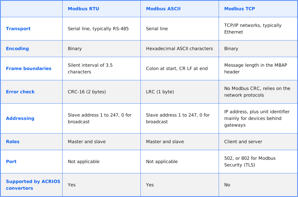
The three variants carry the same Modbus message in different frames.
Modbus RTU transmits data in compact binary form. A frame contains the slave address, the function code, the data, and a 2-byte CRC-16 check. There is no start or end character: frames are separated by a silent interval of at least 3.5 character times. At baud rates above 19,200 Bd, the specification recommends fixed timing values instead of intervals derived from the character length. RTU is the most widely used serial variant.
Modbus ASCII transmits every byte as two readable hexadecimal characters. A frame starts with a colon and ends with carriage return and line feed, and errors are detected with a 1-byte LRC check. The format is easier to read during troubleshooting, but the same data takes roughly twice as many characters as in RTU.
Modbus TCP sends Modbus application data over a TCP connection and adds a 7-byte MBAP header to every message. The header contains a transaction identifier, a protocol identifier, a length field, and a unit identifier. Modbus TCP does not include the Modbus RTU CRC. Instead, it relies on the error-detection mechanisms of the underlying network protocols. Modbus TCP uses port 502, registered with IANA for Modbus traffic. The unit identifier is used mainly when a request needs to reach a device behind a gateway on a serial line.
Neither Modbus RTU nor standard Modbus TCP provides authentication or encryption. Any device with access to the bus or network can send requests. The Modbus Security specification defines a TLS-based variant of Modbus TCP, using port 802. Both communicating devices must support it.
RS-485 as the physical layer
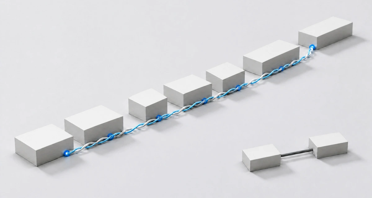
Modbus RTU and ASCII define how messages are framed, not how electrical signals travel. In practice, the physical layer is usually RS-485, a differential serial interface that allows several devices to share one pair of wires.
A single RS-485 segment supports up to 32 unit loads. The number of connected devices depends on their electrical loading, not only on their Modbus addresses. The bus is terminated at both ends, typically with 120 Ω resistors, and bias resistors keep the line in a defined state when no device is transmitting.
These details matter more than they seem. Missing termination, missing bias, or a star topology instead of a line can cause intermittent communication errors that look like protocol problems. More on RS-485 and its role next to M-Bus in the M-Bus, wM-Bus and RS-485 technology guide.
Addressing and common errors
On a serial line, each slave has an address from 1 to 247. Address 0 is a broadcast: it is used for supported commands, typically writes, and the slaves execute it without sending individual responses. Two devices with the same address on one bus will answer at the same time and corrupt each other’s responses.
Most Modbus integration problems fall into a few recurring categories:
- Serial settings: baud rate, parity, and stop bits must match exactly on all devices on the bus. RTU uses 11 bits per character by default
- Register numbering: documentation often uses notations such as 40001 for the first holding register, while the protocol itself addresses registers from zero, so a request can easily end up one register off
- Data format: byte order, word order, scaling, and offsets differ between manufacturers, so a correctly read register can still produce a wrong value
- Wrong table: reading input registers instead of holding registers, or the other way round, returns an exception or unrelated data
- Wiring: missing termination or bias, swapped data lines, or a topology that is not a line
A particular complication in Modbus integration is that the protocol is interoperable at the communication level, but it does not standardise how manufacturers map measurements to registers.
Modbus in industrial meters and energy meters
Modbus is common in electricity meters, heat meters, flow meters, and industrial sensors, especially in installations that already use PLCs or building management systems. Meters typically expose energy totals, instantaneous power, voltages, currents, flows, or temperatures in holding or input registers, described in a register map in the manufacturer’s documentation.
For remote meter reading, this means every Modbus meter type needs its own configuration. Two meters from different manufacturers may measure the same quantity, but store it in different registers, formats, and units.
Bridging Modbus to LoRaWAN and NB-IoT
Modbus RTU devices on RS-485 are usually read locally by a PLC, a controller or a data logger. To read them remotely without cabling to a central system, a converter can act as the master on the RS-485 line, read the defined registers, and send the values over a wireless network.
The difference between a converter, a bridge and a gateway is explained in converter, bus, bridge, gateway: what’s the difference?
ACRIOS converters for Modbus to LoRaWAN and Modbus to NB-IoT work on the serial side: they support Modbus RTU and Modbus ASCII over RS-485, not Modbus TCP. Communication speeds are configurable from 300 to 115,200 Bd, and one converter can read up to 96 devices on a single line.
Because Modbus has no auto-discovery, the register map of each device is defined in a device library through the Lua scripting interface, including byte order and offsets, so the data arrives in a unified structure. The configuration, including the device library and reading intervals, can be changed remotely. Versions with an auxiliary supply can power a connected RS-485 sensor from 5 to 24 V DC.
The choice of network follows the site. LoRaWAN converters send standard Class A packets to any compliant network server and require access to a private LoRaWAN gateway or coverage from a public LoRaWAN network. NB-IoT converters work with an operator SIM card and send data without a gateway. Technical documentation and integration manuals are available on the ACRIOS wiki.
Which Modbus variant fits where
Modbus RTU remains the typical choice where meters and sensors sit on an RS-485 line in a plant room, a substation or a distribution cabinet. Modbus TCP fits where devices are already connected to an IP network and integrated into SCADA or building management systems. Modbus ASCII appears mainly in older equipment.
For remote reading, the variant decides the hardware path. Serial Modbus devices can be bridged to LoRaWAN or NB-IoT directly at the RS-485 line. In every case, the success of the project depends less on the protocol than on knowing the register map of each device before the first reading is attempted.

Glossary of terms used
- Coil: a single-bit Modbus value that can be read and written
- CRC (cyclic redundancy check): a 2-byte error check at the end of every Modbus RTU frame
- Discrete input: a single-bit Modbus value that can only be read
- Function code: the part of a Modbus message that defines which action the device should perform, such as reading holding registers
- Holding register: a 16-bit Modbus value that can be read and written
- Input register: a 16-bit Modbus value that can only be read
- LRC (longitudinal redundancy check): a 1-byte error check used in Modbus ASCII frames
- MBAP header: the 7-byte Modbus Application Protocol header added to every Modbus TCP message
- RS-485: a differential serial interface that allows several devices to communicate over one shared pair of wires
- Unit identifier: a field in the MBAP header used mainly to address a device behind a gateway on a serial line
FAQs
Modbus meters and sensors on RS-485 can report remotely once their register maps are defined. We can review the devices on site and prepare a converter configuration for LoRaWAN or NB-IoT.

Blog
RS-485, RS-232 and RS-422: key differences

ILI: what the EU leakage threshold measures
Pulsed water meter: All you need to know

LoRaWAN airtime: why radio conditions matter
Converter, bus, bridge, gateway: what's the difference?

What actually drains an IoT device battery
M-Bus parsing strategies for LoRaWAN and NB-IoT

How to best replace walk-by meter reading

Can your existing meters be retrofitted?

Battery life in IoT: beyond the datasheet number

Agile, Waterfall, or NRE? Choosing a development methodology

Developing adaptive IoT communication under the CRA

Focused supplier or large vendor? Depends on the project

Edge computing in IoT metering

Manufacturer as a technology partner

Why a device without an antenna fails

CE certification for IoT: What RED DA changes

Water losses in utility networks: The hidden cost of leaks

Pressure monitoring in water networks: Early fault detection

M-Bus pressure sensor: Leak detection for water utilities

The cost of measurement data errors and how to prevent them

Smart Readiness Indicator (SRI): All you need to know
M-Bus installation tool Wizard from ACRIOS

Coulomb meter: Everything you need to know

ACR-EX in water utilities: remote reading of pulse water meters

ACRIOS and Quectel announce partnership

External or internal? How custom development works

Proven deployment of 10,000 wM-Bus converters for EED

Choosing a remote reading system for water utilities

Open data interfaces pay off for reporting and integration

15-minute vs daily meter readings frequency explained

Scripting in IoT: Flexibility, sustainability, and protection

Gas meter data to dashboard: ACR-EX meets Datacake

EPBD is coming: what BACS means for your building

When DTLS makes sense. Know before you deploy

Not your keys, not your hardware
868 MHz or 433 MHz? The right choice for your wM-Bus
Everything you need to know, documented. ACRIOS wiki.

End-to-end custom hardware and software development
How to collect energy data to support ISO 50001

Lowering IoT TCO through smart manufacturing

Reading Sensus meters with zero hardware changes

Why 15-minute data matters in district heating

Give me a tool that works. Not a manual.

5 most common myths about remote meter reading

Battery-powered vs wired: What really costs more?

Cyber Resilience Act and IoT hardware

Next-gen meter readings, no replacements needed

Modernising metering infrastructure

M-Bus to IoT integration explained

Understanding TCO: More than just hardware

NB-IoT technology: All you need to know

LoRaWAN: All you need to know

M-Bus, wM-Bus, and RS-485: A technology guide

LoRaWAN vs. NB-IoT: Which technology is right for you?

Smart metering: What it is and why it matters

IoT: Technology that saves time and money