RS-485, RS-232 and RS-422: key differences
How single-ended and differential serial interfaces compare, and how to wire, terminate and connect them correctly
RS-232, RS-422 and RS-485 often share the same connectors, appear in the same datasheets and are sometimes treated as interchangeable. They are not. A device that works perfectly on a short RS-232 cable can fail on a 50 m run, and an RS-485 bus that communicates in the workshop can drop messages once it is installed next to power cables in a plant room.
The differences come down to how each interface represents a signal on the wire, how many devices it allows and what the cable needs around it. Understanding these points makes it easier to choose the right interface, wire it correctly, and recognise the most common causes of field failures.
Key takeaways
- RS-232 is a single-ended, point-to-point interface for short distances. RS-422 and RS-485 are differential interfaces that carry data over much longer cables and tolerate electrical noise far better.
- RS-422 connects one driver to up to 10 receivers. RS-485 allows multiple drivers on one bus, with up to 32 unit loads per segment and more with fractional-unit-load transceivers.
- Differential interfaces support up to 10 Mbps or up to around 1,200 m, but not both at once. Longer cables mean lower data rates.
- An RS-485 bus is wired as a line and terminated at both ends. Where external bias is needed, it is applied at one point, and typical non-isolated installations also carry a common reference conductor.
- RS-232 has a standardised DB9 pinout. RS-422 and RS-485 do not, and manufacturers use the A and B labels inconsistently, so device documentation always decides.
- Most field problems come from wiring, termination, bias and grounding rather than from the devices themselves.
Single-ended and differential transmission
RS-232 is single-ended. Each signal travels on one wire and is measured against a common ground. Any noise picked up by the wire, or any difference in ground potential between the two devices, directly affects the signal the receiver sees.
RS-422 and RS-485 are differential. Each signal uses a pair of wires, and the receiver evaluates only the voltage difference between them. Noise that affects both wires of a twisted pair similarly is largely rejected by the differential receiver because it evaluates the voltage difference between them. This is the main reason why differential interfaces reach much longer distances and work reliably in electrically noisy environments.
RS-232, RS-422, and RS-485 define only the electrical layer. They specify voltages, loads and signalling, not the data format. Protocols such as Modbus RTU run on top of them.
RS-232: point-to-point over short distances
RS-232 connects exactly two devices. In its classic form, one side is the data terminal equipment (DTE), such as a computer, and the other is the data circuit-terminating equipment (DCE), such as a modem or an instrument. Data is sent over separate transmit and receive lines so both directions can operate at the same time.
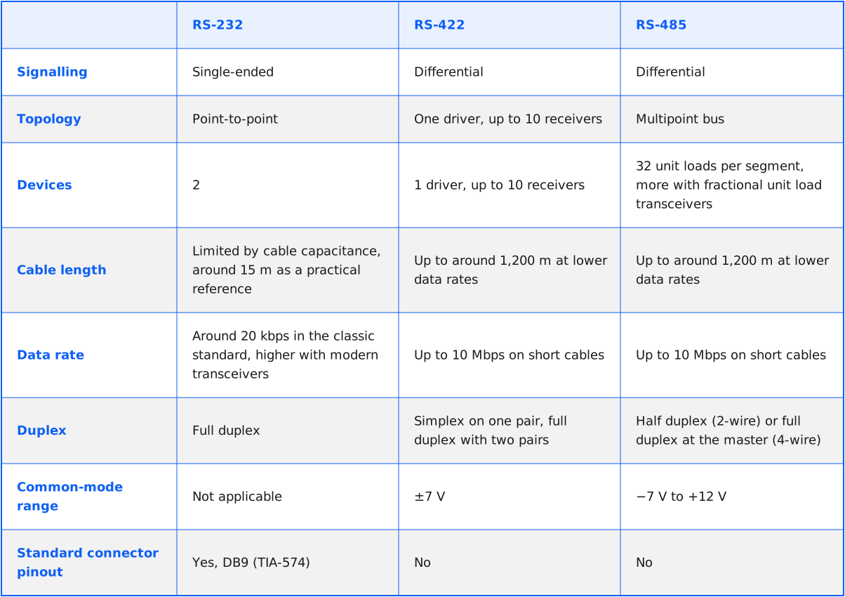
Signal levels are bipolar: a logic 1 is a negative voltage and a logic 0 is a positive voltage, with driver levels between 3 V and 15 V in either polarity. Because the signal is referenced to ground, cable length is limited, mainly by cable capacitance and data rate. Around 15 m is a common practical reference, but the achievable distance depends on the cable and installation. RS-232 remains common for configuration ports, service interfaces and older instruments.
RS-422: differential, one driver and several receivers
RS-422 uses differential pairs and supports data rates up to 10 Mbps and cable lengths up to about 1,200 m (4,000 ft). It supports one driver and multiple receivers on a differential pair, up to 10 receivers in total. For bidirectional point-to-point communication, you can use two pairs, enabling full-duplex operation.
RS-422 suits point-to-point links over long distances, or one transmitter broadcasting to several listeners. It does not support several transmitters sharing one pair.
RS-485: the multipoint bus
RS-485 builds on RS-422, with one decisive difference: its drivers can be switched off when they are not transmitting. This lets several devices take turns on the same pair of wires, making RS-485 a true multipoint bus. It also extends the common-mode voltage range to −7 V to +12 V so that devices can tolerate larger ground potential differences.
A standard RS-485 segment supports up to 32 unit loads. Many modern transceivers present only a fraction of a unit load, so a segment can carry 64, 128, or up to 256 devices, depending on the transceivers used. RS-485 is the most common physical layer for Modbus RTU and for many industrial and metering devices.
Distance, speed and number of devices
The headline figures for RS-422 and RS-485, up to 10 Mbps and up to around 1,200 m, cannot be reached at the same time. The maximum data rate applies to short cables of around 12 m, while the maximum length applies at around 100 kbps. In practice, the achievable combination depends on the cable, its capacitance, the transceivers and the electrical environment.
For typical metering and automation installations, this trade-off is rarely a problem. Modbus RTU devices commonly operate at speeds from 9,600 to 115,200 Bd. The appropriate speed depends on the cable length, transceivers and installation conditions.
The number of devices depends on electrical loading, not only on addressing. A protocol may allow up to 247 addresses, but the bus segment must still stay within the unit load limit of its transceivers.
2-wire and 4-wire wiring
RS-485 is most often installed as a 2-wire bus. One twisted pair carries data in both directions, and the devices take turns transmitting. This is half-duplex communication, used for example by Modbus RTU.
A 4-wire installation uses two pairs with different roles. In a typical master and slave arrangement, the master transmits on one pair to the receivers of all slaves, while the slaves transmit on a second, shared pair back to the master’s receiver. Only one slave may transmit on the return pair at any moment. The master can therefore send and receive at the same time, but the slaves still take turns.
In typical non-isolated installations, a common reference conductor is also provided alongside the data pairs to keep the transceivers within their permitted common-mode voltage range. This means a conventional 2-wire RS-485 connection uses a data pair plus common, while a 4-wire connection uses two data pairs plus common. Isolated interfaces may require a different grounding arrangement.
The bus should be wired as a line, running from one device to the next. Star and tree topologies, and long branches to individual devices, create signal reflections that can corrupt data.

Termination, bias, shielding and grounding
A termination resistor at each physical end of the bus matches the cable impedance and prevents signal reflections. A value of 120 Ω is common, matching the characteristic impedance of typical twisted-pair cable, but the termination must match the cable and the system documentation. For Modbus installations, the Modbus over Serial Line specification describes its own termination options, including 150 Ω or a combination of a 120 Ω resistor and a series capacitor. Termination belongs only at the two ends of the line, not at every device.
Bias resistors, also called fail-safe bias or line polarisation, hold the bus in a defined idle state when no device is transmitting. Without them, an idle line can float, and receivers may interpret noise as data. Where external biasing is required, it should be implemented at one location on the bus.
The Modbus over Serial Line specification gives pull-up and pull-down resistor values of 450 to 650 Ω for its specified arrangement. Some modern transceivers provide built-in fail-safe behaviour, so external biasing requirements should be checked against the device documentation.
Twisted-pair cable is used for reliable transmission because it helps limit the effect of electromagnetic interference. Shielding can further improve immunity, especially in environments with higher interference levels. Shielding and grounding should follow the equipment manufacturer’s EMC and installation guidance.
Some installations use single-point shield grounding to limit low-frequency ground-loop currents, while other systems require bonding at both ends. The cable shield must not be treated as a substitute for the signal reference conductor.

Pinout: DB9 and RJ45
For RS-232, the 9-pin DE-9 connector, commonly called DB9, has a standardised pin assignment defined in TIA-574. From a DTE device, the three essential pins are pin 2 (receive data, RXD), pin 3 (transmit data, TXD), and pin 5 (signal ground). The remaining pins carry handshake and modem control signals. When two DTE devices are connected directly, a null-modem cable crosses the transmit and receive lines.
RS-422 and RS-485 have no standardised connector pinout. The standards define electrical characteristics, not connectors, so DB9, RJ45 and screw terminal assignments differ between manufacturers. The Modbus over Serial Line specification defines one specific RJ45 assignment for Modbus devices, with D1 on pin 4, D0 on pin 5 and the common conductor on pin 8. This is a Modbus assignment, not a general RS-485 pinout, and many RS-485 devices use different pins.
The signal names add a further source of confusion. The Modbus specification uses D0 for the inverting line and D1 for the non-inverting line. Many manufacturers label the lines A and B, or + and −, and the A and B assignment is not used consistently. The device documentation is always the reference, not the label alone.

Common mistakes in the field
Most RS-485 problems in the field are wiring problems, not device faults:
- Swapped data lines: because A and B labels are inconsistent, crossed lines are one of the most frequent causes of a silent bus
- Termination in the wrong place: missing termination at the ends, or termination switched on at every device, distorts the signal
- Bias missing or duplicated: no bias leaves the idle line undefined where the transceivers need it, while several bias networks overload the bus
- Wrong topology: star wiring and long branches cause reflections that appear as intermittent errors.
- No common reference: connecting only the data pair can push non-isolated devices outside the common-mode range, especially between separate cabinets or buildings
- Shield used as the signal reference: the cable shield is not a replacement for the common conductor, and grounding should follow the manufacturer’s guidance
- RS-232 cable too long: an RS-232 link that works on the bench may fail once the cable is extended in the installation
Configuration errors add to these. Baud rate, parity, and stop bits have to match on all devices, and in a protocol such as Modbus, the register maps have to be correct as well, as explained in Modbus RTU vs TCP: All you need to know. The simpler the on-site configuration process, the fewer such errors occur, as described in Give me a tool that works. Not a manual.
When a converter makes sense
A converter is needed where two interfaces meet. A typical case is a device with an RS-232 port that has to communicate over a longer distance or join a multipoint bus. An RS-232 to RS-485 interface converter adapts the electrical signalling, but the devices must still use compatible serial settings and a protocol suited to the resulting connection.
A different case is an RS-485 device that needs to be read remotely without cabling to a central system. Here the converter reads the data on the RS-485 line and sends it over a wireless network.
ACRIOS converters for Modbus to LoRaWAN and Modbus to NB-IoT work in this way with Modbus RTU and Modbus ASCII devices on RS-485. Communication speeds are configurable from 300 to 115,200 Bd; one converter can read up to 96 devices on a single line, and the register map of each device is defined in a device library through the Lua scripting interface. Versions with an auxiliary supply can power a connected RS-485 sensor from 5 to 24 V DC.
For more on RS-485 alongside M-Bus and wM-Bus, see the M-Bus, wM-Bus and RS-485 technology guide.
Which interface fits where
RS-232 remains the practical choice for short point-to-point connections, such as service and configuration ports. RS-422 fits long point-to-point links or one transmitter with several listeners.
RS-485 is the standard choice when several devices share one cable over longer distances, making it the typical physical layer for meters, sensors, and controllers in plant rooms and distribution cabinets.
Whichever interface is used, reliable communication depends less on the standard itself than on the installation: the right cable, a line topology, correct termination and bias, and grounding that follows the equipment documentation.

Glossary of terms used
- Bias resistors: a pull-up and pull-down resistor pair that holds an RS-485 bus in a defined idle state when no device is transmitting
- Common-mode voltage: the average voltage of both lines of a differential pair relative to ground, which the receiver must tolerate within its specified range
- DTE and DCE: data terminal equipment and data circuit-terminating equipment, the two roles of devices in a classic RS-232 connection
- Differential transmission: signalling over a pair of wires in which the receiver evaluates only the voltage difference between them
- Full duplex: communication in which both directions can transmit at the same time
- Half duplex: communication in which devices take turns transmitting over the same lines
- Single-ended transmission: signalling in which each signal is carried on one wire and measured against a common ground
- Termination resistor: a resistor at each end of a bus that matches the cable impedance and prevents signal reflections
- Twisted pair: two conductors twisted together so that external noise affects both equally
- Unit load: a measure of the electrical load a single receiver places on an RS-485 bus, used to calculate how many devices a segment supports
FAQs
RS-485 meters and sensors can be read remotely without new cabling to a central system. ACRIOS can review the devices and the bus on site and prepare a converter configuration for LoRaWAN or NB-IoT.

Blog
Modbus RTU vs TCP: All you need to know

ILI: what the EU leakage threshold measures
Pulsed water meter: All you need to know
LoRaWAN airtime: why radio conditions matter
Converter, bus, bridge, gateway: what's the difference?
What actually drains an IoT device battery
M-Bus parsing strategies for LoRaWAN and NB-IoT

How to best replace walk-by meter reading

Can your existing meters be retrofitted?

Battery life in IoT: beyond the datasheet number
Agile, Waterfall, or NRE? Choosing a development methodology

Developing adaptive IoT communication under the CRA

Focused supplier or large vendor? Depends on the project

Edge computing in IoT metering
Manufacturer as a technology partner

Why a device without an antenna fails

CE certification for IoT: What RED DA changes

Water losses in utility networks: The hidden cost of leaks

Pressure monitoring in water networks: Early fault detection
M-Bus pressure sensor: Leak detection for water utilities

The cost of measurement data errors and how to prevent them

Smart Readiness Indicator (SRI): All you need to know
M-Bus installation tool Wizard from ACRIOS

Coulomb meter: Everything you need to know
ACR-EX in water utilities: remote reading of pulse water meters

ACRIOS and Quectel announce partnership

External or internal? How custom development works

Proven deployment of 10,000 wM-Bus converters for EED

Choosing a remote reading system for water utilities

Open data interfaces pay off for reporting and integration

15-minute vs daily meter readings frequency explained
Scripting in IoT: Flexibility, sustainability, and protection

Gas meter data to dashboard: ACR-EX meets Datacake
EPBD is coming: what BACS means for your building
When DTLS makes sense. Know before you deploy

Not your keys, not your hardware
868 MHz or 433 MHz? The right choice for your wM-Bus
Everything you need to know, documented. ACRIOS wiki.
End-to-end custom hardware and software development
How to collect energy data to support ISO 50001

Lowering IoT TCO through smart manufacturing

Reading Sensus meters with zero hardware changes

Why 15-minute data matters in district heating

Give me a tool that works. Not a manual.

5 most common myths about remote meter reading

Battery-powered vs wired: What really costs more?

Cyber Resilience Act and IoT hardware
Next-gen meter readings, no replacements needed

Modernising metering infrastructure

M-Bus to IoT integration explained

Understanding TCO: More than just hardware

NB-IoT technology: All you need to know

LoRaWAN: All you need to know

M-Bus, wM-Bus, and RS-485: A technology guide

LoRaWAN vs. NB-IoT: Which technology is right for you?
Smart metering: What it is and why it matters

IoT: Technology that saves time and money